draw holes in 3d autocad
In this series of posts, I'll be providing tips that bear witness how to do something in both AutoCAD and BricsCAD, hence A & B.

The Series
The thought backside this serial is to provide useful information for several sorts of reader:
- AutoCAD users.
- BricsCAD users.
- People in the process of transitioning from AutoCAD to BricsCAD and who need to know what to practice differently (if anything).
- People considering transitioning from AutoCAD to BricsCAD and who want to know about the differences and similarities.
Drilling holes
This post explains how to put holes in your 3D models. This post volition cover some fairly straightforward topics but I intend to cover more involved details in future posts. I'll assume you take a bones agreement of creating 3D primitives and the boolean operations (union, decrease and intersect). I will be using the 3D Modeling workspace in both AutoCAD and BricsCAD. I'm going to first with the dynamic UCS characteristic turned off and the 2D Wireframe visual fashion.
Vertical cylinder subtraction
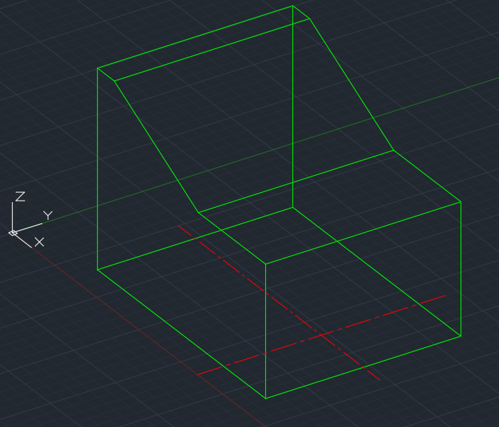
Allow's accept the simplest case. You have a solid and you but want to identify a cylindrical hole in a known location that you already take geometry you tin can snap to. For case, you want to drill a DIA 40 hole correct through this part, using the centerlines shown:
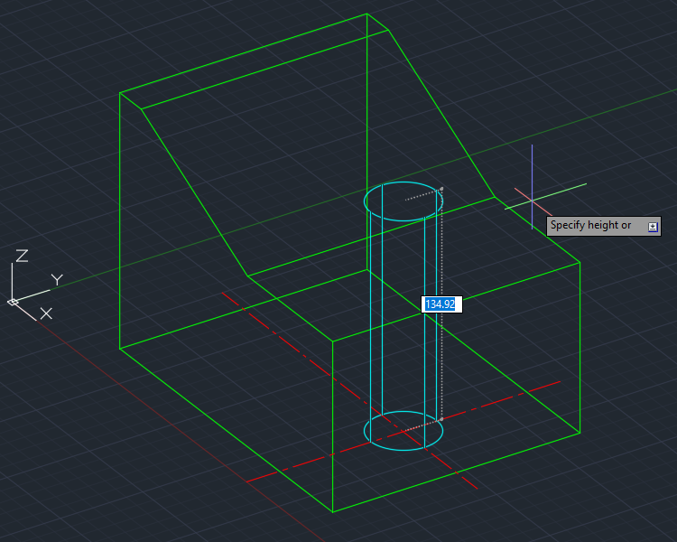
Start with the CYLINDER command:
Pick the intersection of the two centerlines, enter a radius of 20 and a meridian of 100. You lot don't take to be precise with the height, y'all can simply betoken to any top that's over 100:
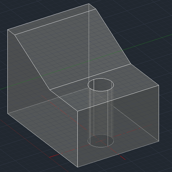
To create the pigsty, apply the Decrease command:
With this command it's important to select the objects in the right order. Select the object(southward) you're substantiating from first, then press Enter to terminate the pick procedure for those objects. Then select the object(s) you're subtracting and printing Enter to finish that selection process. That will requite you your hole (temporarily switched to X-Ray visual style for clarity):
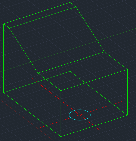
Extruding a circumvolve
Instead of creating the cylinder diectly, you tin instead extract a circumvolve. This is an extra step if yous don't already have a circle of the right size in the right place, only less piece of work if you practise. For example, if you're converting a 2d cartoon to a 3D model, you'll probably have the circle already.
Invoke the EXTRUDE control:
Select the circle, printing Enter to stop the pick (considering you can extrude several objects at once) and specify a tiptop of at least 100, every bit with the CYLINDER control. Subtract the resultant cylinder and you're done.
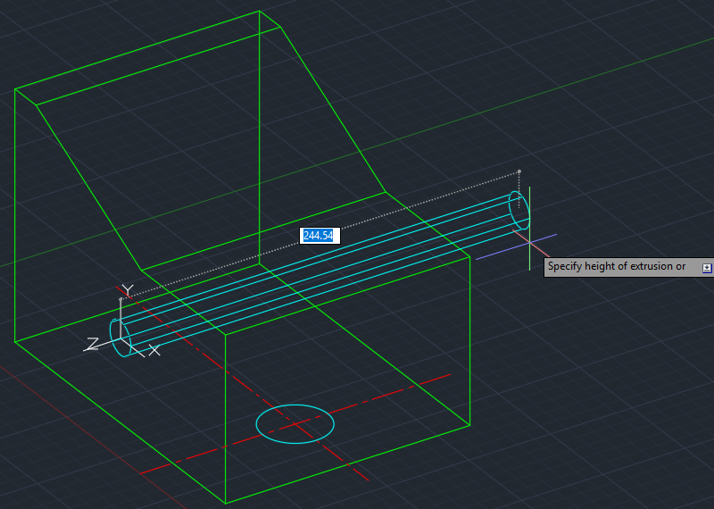
It's important to notation that extrusions work perpendicular to the aeroplane of the object(s) being extruded. In this case the cylinder is created vertically considering the circumvolve lies flat (in terms of the Earth Coordinate System). If you lot have a circumvolve lying in a different plane, the extrusion will be perpendicular to that plane. For example, here a circle that lies in a vertical plane is being extruded horizontally:
Cartoon a circle in the other planes
That'due south all well and adept if you lot take a circle in the right plane, just what if y'all need to draw i? You accept several alternatives.
I method is to depict your circle in whatever plane you like, then utilise the ALIGN control to move it into place. That works, just it's not that efficient.
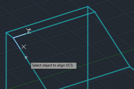
Alternatively, you tin can change your UCS to marshal with your desired plane, and so merely describe your circumvolve. That tin be fiddly, but if y'all take a handy solid object containing the airplane you want to draw in, you can utilize the UCS command's OBject pick (hot tip: E for Entity does the same thing). By advisedly hovering over the airplane, you tin ready your desired UCS with one click and a lot less tiresome fiddling around than trying to work out what the other (somewhat arcane) options of the UCS command all mean. Hither, the UCS control'south OBject option is shown in activity:
Notation that this is an example of one of the very few things that works in AutoCAD simply not BricsCAD. The UCS command'south OBject (and Entity) pick exists, but you can't use it to align a UCS with a solid's face. You tin can, however, utilize the UCS command'due south Face option. That exists in both applications, but I adopt the fashion it works in BricsCAD where the origin of the UCS is placed in one corner of the face with no further interaction required. In AutoCAD, the default is to place the UCS origin at some random point you used to select the face up and then if you demand to locate points precisely at that place is a bit more messing effectually required.
Effect: Use UCS East in AutoCAD and UCS F in BricsCAD.
In any case, there are other, more than efficient means to skin this particular cat. In my view, the nearly efficient style of cartoon an object in a given plane, where that airplane exists on a 3D solid, is to use Dynamic UCS. I'll explain that, and how to push and pull your holes into submission, in the next post.
Source: https://www.cadnauseam.com/2018/08/28/a-b-tip-7-drilling-holes-1/
0 Response to "draw holes in 3d autocad"
Post a Comment